Sidecars, Leading Links, and Adaptions Designed and Built here in the USA
What we've been doing this week
Week 24
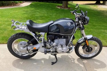
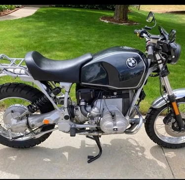
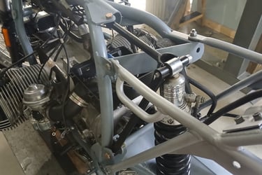
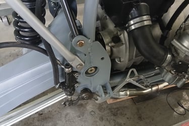
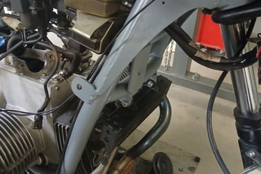
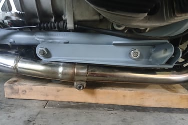
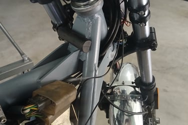
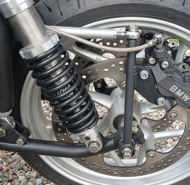
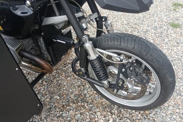
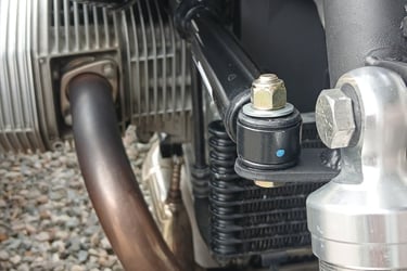
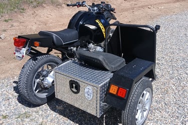
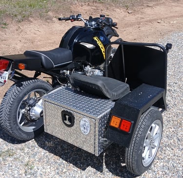
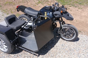
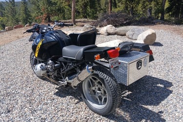
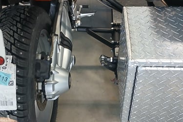
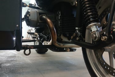
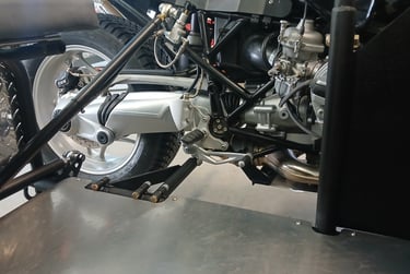
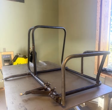
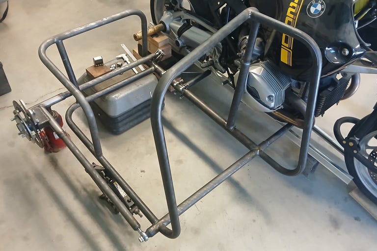
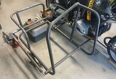
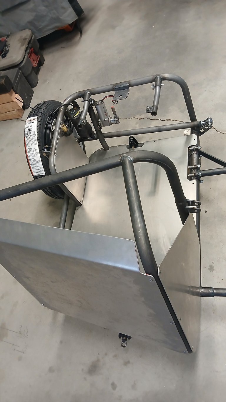
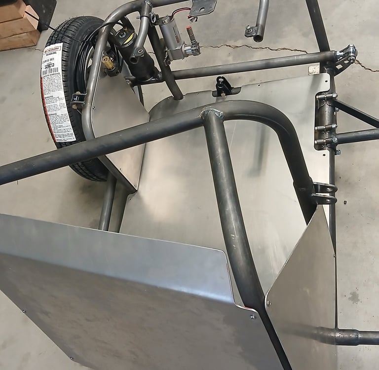
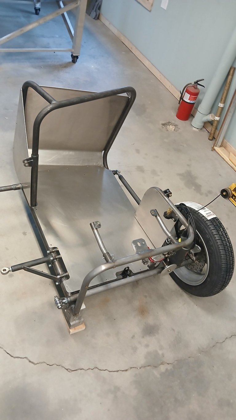
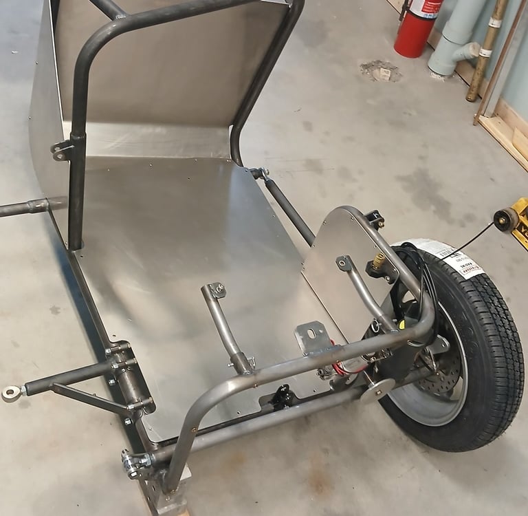
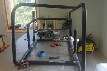
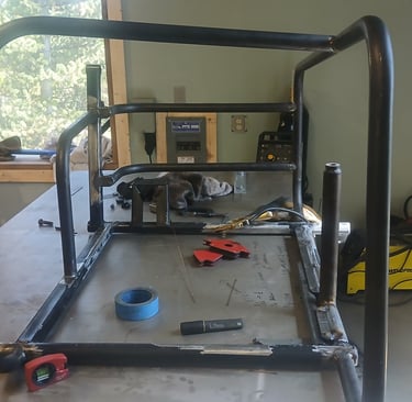
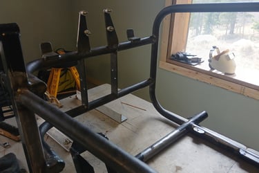
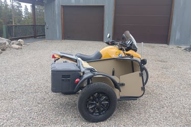
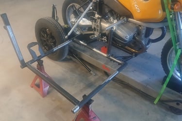
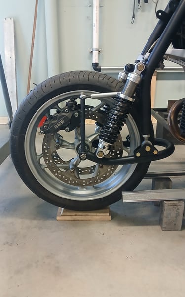
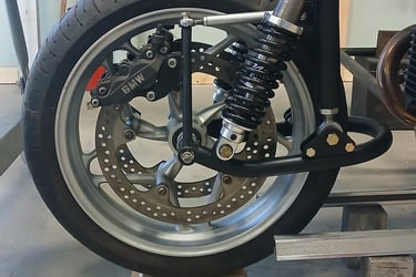
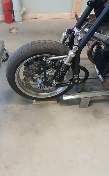
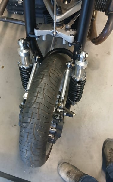
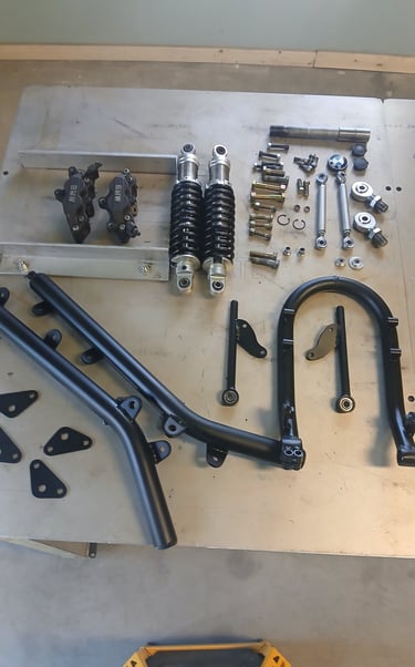
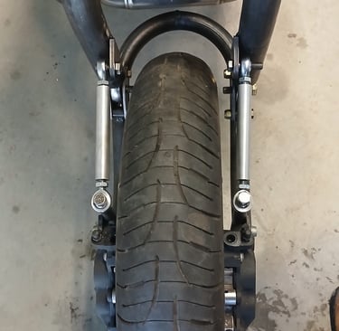
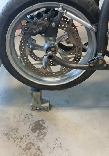
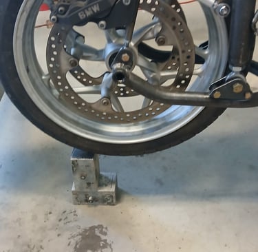
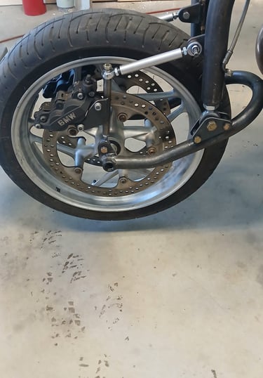
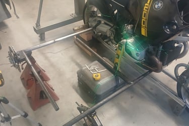
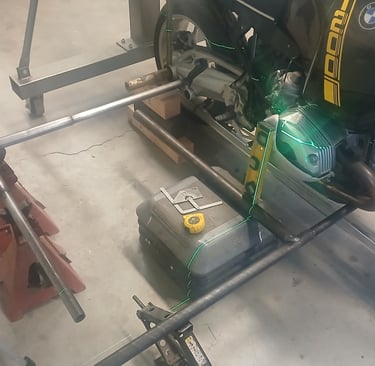
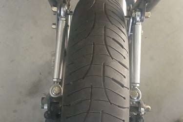
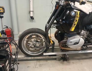
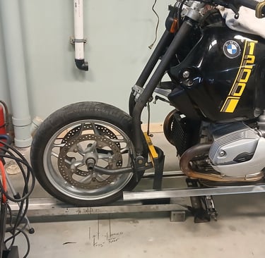
Aside from testing out the hybrid GS outfit, the last couple of weeks have been distracted with chores. However, we have picked up a rather nice low milage R100R cafe racer. Work is now well underway to prepare the airhead for its sidecar. The bike is striped back to the bare frame, and reinforcement is added to the swing arm pivot area, and headstock area. Also bracketry is added for the rear shock, as a R1100 swing arm and final drive is being added (this combined with a short first gear will give the lowest ration available on any BM). Rear brake uses a G310 master cylinder and modified GS lever, torsion bar is being replaced with an adjustable heim jointed unit. Bracketry for the 4 mounting (all reinforced) is also added. Fork trees are sourced from a VMAX 43mm with a generous offset to clear the gas tank, leading links with a very long travel will complete the front end, as this outfit is being built primarily for the trails. The engine casings and timing cover have been machined to reduce unnecessary clutter, and a modern alternator and ignition system will be fitted. Early design solutions are underway for a belt driven alternator, watch this space:)
Week 21
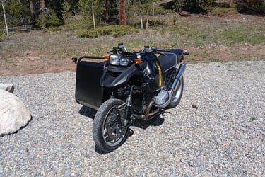
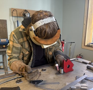
Testing out the GS hybrid, while the outfit runs great on the smooth stuff any speed on the rough was causing some serious front end instability. Whilst this could likely be sorted with a good steering damper, I wanted to get perfect stability without first, such that the damper only needs to manage very high speed issues. So it was time to bite the bullet and accept that a lower leg cross brace was needed. I had been trying to avoid the cross brace because it adds complication and controlling heat distortion was always going to be a challenge. However, seems the pursuit of reduce trail and associated stability loss does require it. Fly screen finally arrived and installed.
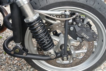
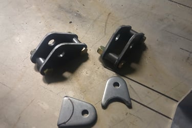
Three sets of leading links now on the go, these are built to suit a conventional telescope conversion, this time with fixed calipers, lighter shocks, and more suspension travel.
Week 20
Finishing touches on the GS hybrid, which took a lot of time (wiring tidy up, brake and fuel system fettling). Just waiting on a front screen and dash to finish it up.
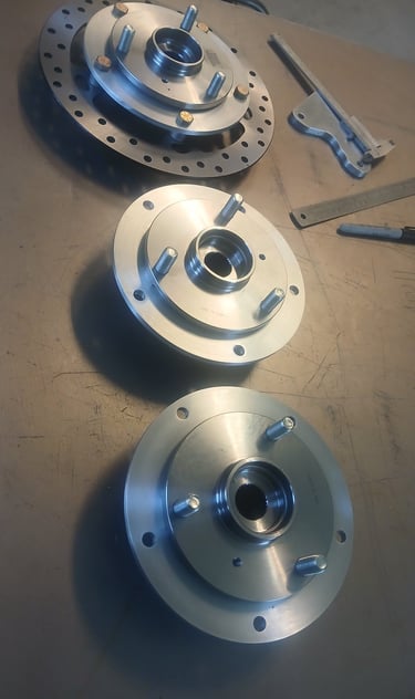
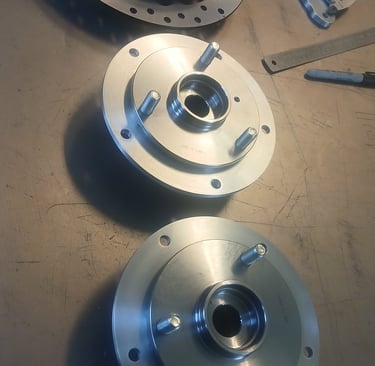
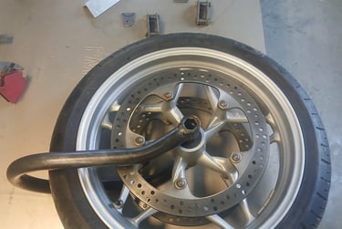
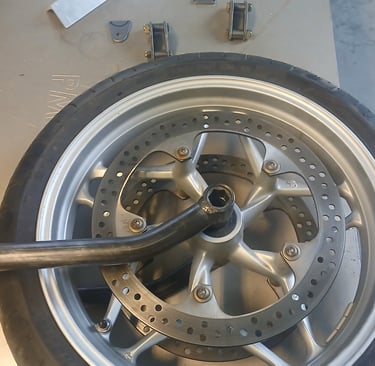
Have been experimenting with the smaller 220mm brake rotor and Bremo mini caliper, to reduce the effort / time to machine the mounting components. I think I have a combination figured out that should help keep the cost down, while looking fairly awesome as a finished item.
Week 19
GS hybride has had my focus this week. After a carb rebuild (has been sitting for over months), and battery charge it fired right up, and after some balancing and tweaking, its running perfectly. Had to fab up some aluminum bracketry and such to get the GS beak mounted up. Will be installing braided hoses throughout and some wiring to tidy up the motogadget, then will be ready for test riding.
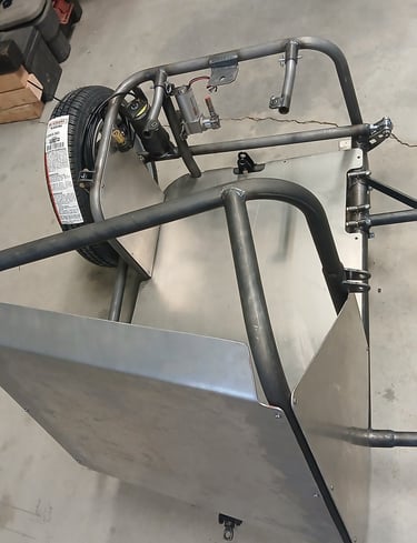
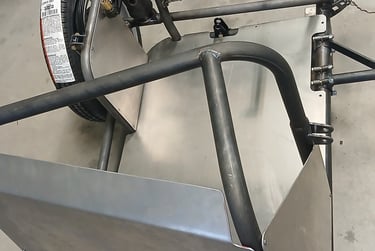
Sidecar chassis was blasted, primed and finish painted, and assembly now well underway. Have been experimenting some with coating schemes for the aluminum paneling, and have settled on a four part scheme which had a very robust top coat that should work well, and looks awesome against the satin black chassis.
Aiming to have this build finished up by next weekend, and will be used as a demo for both sidecar builds and leading links.
Week 18
Finishing up all the add-ons to the modular build. Fabrication is now complete, awaiting blasting and painting. After hours of searching for a suitable aluminum fender, I decided to just bite the bullet and build my own. Will need a little practice on TIG welding aluminum sheet, as it requires AC, but will allow me to build a fender ideally suited and will be 0.09" formed sheet, rather than the thin fenders available on-line.
Modular chassis two and three now fabbed up with a few minor tweaks, based on lessons learnt on previous builds. Hand rails, seat and luggage mounts are not added, allowing customer variations to be chosen. My plan is to try and always have two chassis in stock ready to build up.
Unit trail/radius arms fabbed up with a lighter design of hub interface, the shock mounts are moved further back, and the upper mount is now combined with the tubular upper fender mount. Limit strap will now use the same mounting points as the shock.
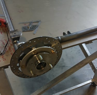
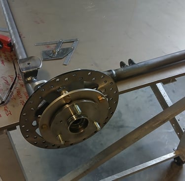
Brake caliper is now the dual pot Brembo mounted off a custom aluminum mount, and the rotor is mounted off a custom aluminum adaptor plate, requiring a lot of accurate machining work.
Week 13
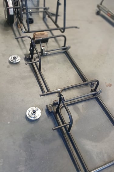
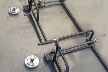
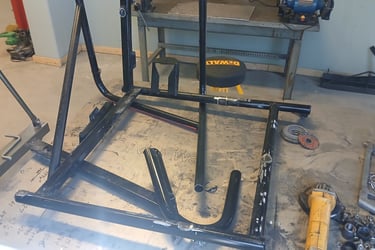
Back onto the modular platform build. Base structure and unit trailing and radius arm now complete, and component mounts being added.
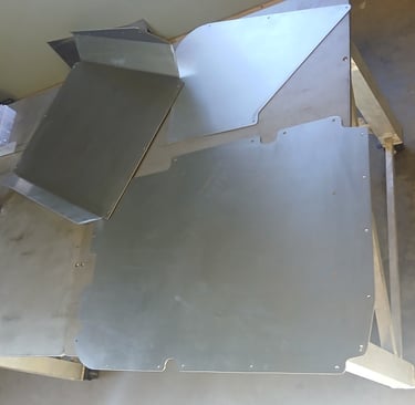
Aluminum panels fresh off the sheet metal brake, all drilled to match the tubular chassis. Basic sidecar offering will have a simple front panel, and floor plate. Upgrade version will have matched and joined front and floor panel with an inboard panel to keep the front wheel spray at bay.
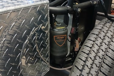
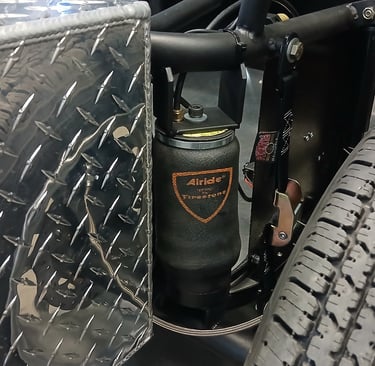
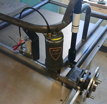
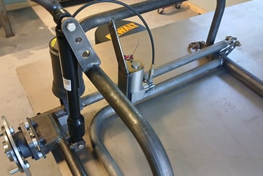
Next onto the bracketry for the chassis. Airbag is mounted off upper and lower perches with access to the airline. Shock is mounted further forward to reduce its damping effect and allow a full 7" of travel for the wheel. Finally an adjustable limit strap is included to the travel to be limited for on-road use.
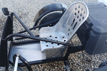
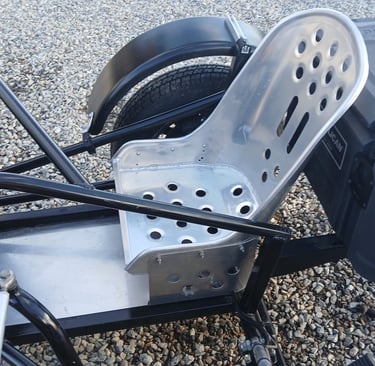
The seat mount is off a pair of spigoted posts that are removable to give full load space access when not being used. The seat itself is a low back molded design that is both robust and water resistant.
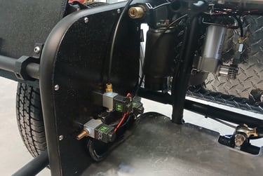
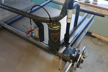
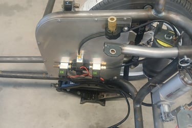
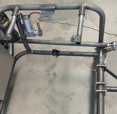
Finally, mounting for the Viair compressor. The air system will include three solenoid valves, controlled by a handlebar switch for trim control, and a quick connect chuck and switch to facilitate on-board air for tire inflation and such.

Week 12
Following a week off it was back to work on the sidecar conversion project. New massive rail loops were added, together with rear tubulars to allow mounting of the larger seat base, back rest, and rear cargo box. New reaction post and new links were made to accommodate the additional weight, and the fender mounting was redesigned to accommodate the bicycle rack that will sit above the sidecar wheel. This week its onto the aluminum panels, then blasting and painting.
Week 10
We collected our first clients outfit from Buena Vista this week. This was previously my own personal outfit that was sold privately through FB a few weeks earlier. The new owner contacted us to make some changes to the outfit, primarily to accommodate his dog, but with a few additional requirements mixed in. 1) Keep dog contained / secure when owner pops into a shop, etc, and provide shade. 2) Relocate compressor etc and structure to give full floor space. 3) Extend floor at the front and side. 4) Replace seat with a removable base. 5) Add bike rack and ability to carry a surf board or snow board. 6) Include removable access door to the side. The original request was also to include a cantilever roof, though following discussion it was agreed as impractical. Original upper frame was removed with a lot of grinding and new material is awaited from the steel suppliers.
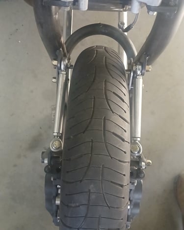
While waiting on material for the sidecar conversion, I finally received the long overdue Hagon shocks for the leading links, so got to work on the mounts, which also involved repositioning the caliper mounts to ensure adequate clearance. Before breaking it all down for shot blasting, I used the my laser tool to check the final trail, which came out at 2-1/2" nuts on, giving me a 2-1/4" if reversing the heim brackets.
Week 9
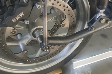
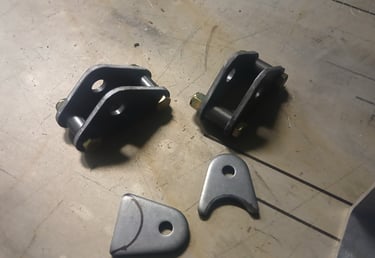
For the caliper mounting I wanted a design that would be truly universal. Typically, the mounting would swivel about the axle, whilst this would be easy enough on my R1200 axle (lots of space on either side of the wheel hub), it would be impossible on models that have a mechanical speedo mechanism on the axle (R1150, R1100, R100, etc), unless of course both calipers where mounted on one side, which is a compromise I can’t live with. Regardless, in addition each swivel / bearing would need to be be-spoke to that particular model $$$.
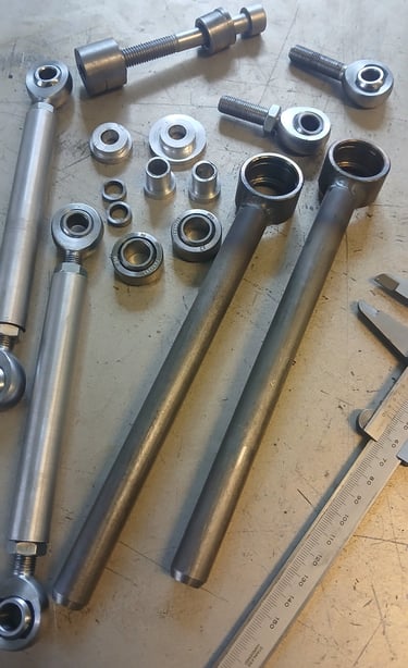
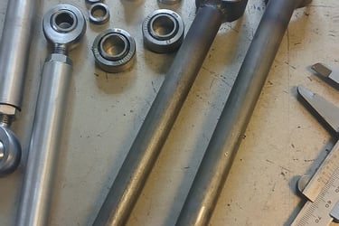
My initial compromise was to use a Heims just above the axle mounted to the swingarm. This arrangement, whilst universal, does mean the calipers will raise and lower on the rotor as the suspension strokes, though only by approx. 1/8” and the positioning has to accommodate that. I have used male Heims either end of a tie rod to accommodate the braking load. I will change this going forward to females and use threaded rod to allow more clearance for the shocks.
After tweaking the geometry some, I managed to get a full 6” of travel without binding or loss of pad contact. However, I was not overly happy with the arrangement, so have decided to instead pivot out-board of the axle with small bearings. Bonus benefit of this is that I can get the tie-rods further in-board allowing the shock mountings to be a little narrower. Just waiting on the parts to arrive so I can finish up the brakes.


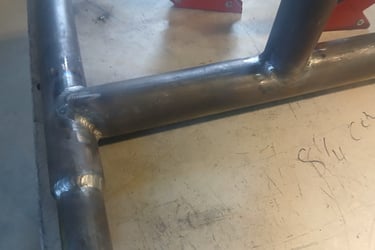
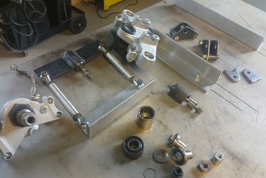
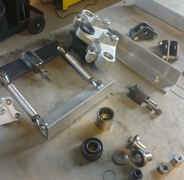
Whilst waiting on parts for the leading links, I got to work on the modular platform sidecar. The extra wheel base from the links has made subtle changes to the sidecar lead and track width, but I think I've got a nice combination of 47-1/2" and 10-1/2". Hoping this will result in nimbleness with good stability. Below are some rather nice coped welds by Finley.
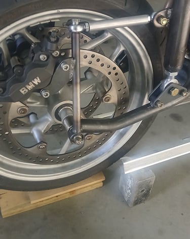
Got the new out-board caliper mounts made and mounted up. Takes a little more work than the above axle pivot, but its a far better and neater solution. You can see how tucked in the tie-rods are, leaving plenty of space for the shocks. Just waiting on the shocks to get the build finished.
Week 8
Seem to have forgot to take pics along the way this week. Anyway first off was to install the new self aligning upper tree bearing, went in a darn site easier than getting the other one out. However, I need to get the ignition switch off so the upper tree could be repainted, and that was a PITA. BMW had used anti tamper screws, and torqued them in so they could never been removed, as such I had to drill them out and replaced them with studs so it could be removed again if necessary.
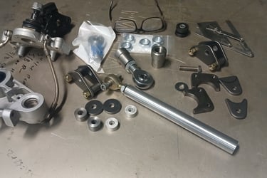
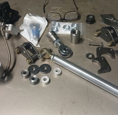
Next I made the lower weld-on brackets for the lower tree using 3/8" plate. Heim joints arrived for the leg pivots, and next I got cracking on the upper attachment for the legs. Here's where I had a Aha moment. Rigidly mounting the upper leg to the upper tree (having already removed the redundant ball joints) would mean load (a lot of load) would go through the upper tree rather than through the lower tree, tele-lever / swingarm, and strut into the frame. The result likely to be a fracture of the upper tree (considering it was never designed to take vertical load). Best solution I can think of is to eliminate the rubber bushing from the strut (replaces the front shock), and use stiff bellville washers between legs and upper tree, this will allow the load to be taken by the lower rather than upper tree.
Last bit for today was to knock out the strut, made from 1" aluminum bar with a solid 3/8" x 1/2" rod end to mount to the tele-lever, simple enough, but yet another machined sleeve needed to keep the narrow rod end in the center (lower shock mount was a lot wider).
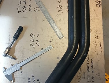
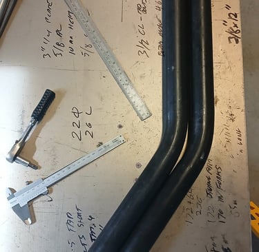
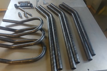
Fork legs bent to ensure symmetry, and tube inserts machined and welded in-place.
To the right, one of several bizzar tools made-up to ensure alignment is assured.
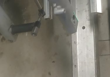
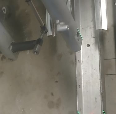
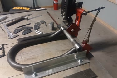
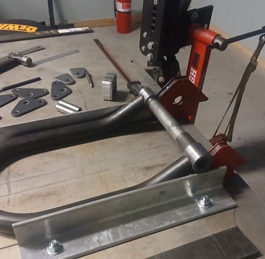
Next I got to work on the bender and I seem to have got bend measuring nailed finally, as the two legs came out identical without any adjustment. Getting the leg mounts perfectly aligned was pains-taking, but the upper and lower tube inserts was a breeze. Once all tacked I had the prodical son finish up the welds. The next step of getting the pivot points aligned was a complete nightmare and took hours before it was ready to tack in place. Lesson learnt here to not use a bolted lower tree (used on the R1200R), but instead to use the GS lower tree which clamps around the fork tubes.
Swing arm set-up ready for tack weld. Getting each leg identical took a lot of (measure, check, measure again), I did a trial run first to get the process down, and this ended up to be within 1/16", so plenty good enough. One axle sleeve is threaded, and the other will be cut to add pinch bolts, allows use of the stock axle.
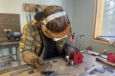
Had Fin do some test runs before welding the sleeve and making the splice. I used a bung to make the splice easier and to guarantee stength in the joining weld. Result turned out just dandy.
Set the swing are to accept a 19" wheel if I later decide to switch out the R1200R wheel. The symmetry end-up nuts on, so should be good to get started on the legs next.
Finished the pivot rough out, this will accept 3/4" heims. Tied a a few other option, bronze insert solid hiems and even a set of custom machined bushings, but the alloy steel heim seemed the best solution for affordability. The pivot brackets are asymmetric to give two trail option (or multiple with custom side plates.
Wow the upper tree did not want to budge, had to make some special tools to pull the pin out, and another special tool to remove the ball joints. Life is a breeze when you have the right tools. The upper tree bearing will be replaced with a self aligning one to allow the tree to follow the solid legs between upper and lower, but also the ball joinst become redundant to I will replace them with sleeves and M12 fasteners to ensure strength.
Week 7
Contact
Mailing Address: PO Box 1959, Fairplay, CO 80440 USA
Phone: 832 588 7869